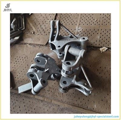
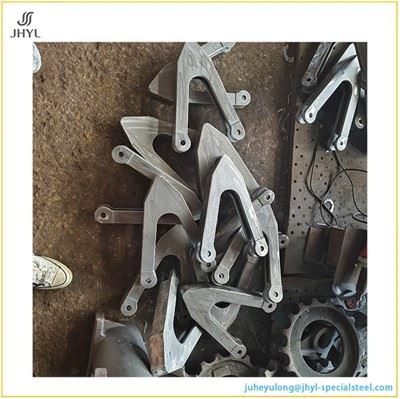
Why ductile iron for a connecting rod
A connecting rod fails in fatigue, not in a single overload. The material choice and the casting process are therefore inseparable from the failure mode.
Ductile iron's spheroidal graphite gives QT450-10 a tensile strength of ≥450 MPa with elongation of ≥10–12% and a yield strength of ≥310 MPa. That combination sits between gray iron and forged steel on the strength–ductility map: enough tensile and fatigue resistance for cyclic combustion loads, with graphite nodules acting as intrinsic crack arresters rather than the flake graphite that makes gray iron brittle under shock. Ferritic QT450-10 is also the grade most commonly specified where impact toughness and dimensional stability matter more than peak tensile - which is exactly the regime of a connecting rod in a diesel or heavy-duty gasoline engine.
What this means for a buyer: the grade name QT450-10 / GGG45 / 65-45-12 does not itself guarantee a reliable rod. The graphite must be nodular, the matrix must be ferritic, and the casting must be sound at the small-end and big-end sections where wall thickness changes. A resin-sand foundry that cannot show nodularity data, CE control records, and section-specific soundness evidence is selling a grade, not a process.
One grade, three standard systems
The same ferritic ductile iron is specified under three systems. A supplier page that lists only "QT450" forces the buyer to do the cross-mapping. This page does it explicitly.
| System | Grade designation | Tensile strength | Yield (0.2%) | Elongation |
|
GB/T 1348 China |
QT450-10 | ≥450 MPa | ≥310 MPa | ≥10% |
|
EN 1563 Europe |
EN-GJS-450-10 / GGG45 | ≥450 MPa | ≥310 MPa | ≥10% |
|
ASTM A536 North America |
65-45-12 | ≥448 MPa | ≥310 MPa | ≥12% |
Data per standard cross-reference tables. Hardness for the ferritic grade typically falls in the 160–210 HB range. If the drawing specifies a European or North American designation, the foundry's process card and material certificate will be issued against that designation, not retrofitted from a Chinese grade at shipment.
Control specific to a fatigue-loaded rod
The mechanical property table is a release criterion. The process controls below are what determine whether those properties are consistent across every rod in the shipment, not just the test bar.
Nodularity and graphite morphology
Nodularity is verified per heat and per casting section on a defined sampling frequency, evaluated to ISO 945 (or the drawing-specified equivalent), with the nodule count and size distribution recorded. A ferritic QT450-10 rod depends on a high nodularity percentage; compacted or vermicular graphite in the wrong location reduces fatigue life without failing the tensile test. The metallographic report should state the evaluation section - small-end, big-end, or shank - because nodularity can vary with section modulus.
Carbon equivalent and melt control before pouring
Thermal analysis (CE meter) is used on the liquid iron before pouring, not inferred from a final chemistry check. For a rod casting, CE is held within a narrow window to balance castability at the thin shank against shrinkage feeding at the thick bosses. The buyer can request CE trend data across a production run as evidence that the window is actually held.
Section-specific soundness
The small-end and big-end are the sections where shrinkage porosity most directly translates into a fatigue initiation site. UT or RT is applied to the rod casting at a defined inspection frequency, with acceptance criteria agreed at PPAP. The relevant question is not whether NDT exists, but whether the inspection section and frequency are written into the control plan for the rod part number, rather than applied as a general foundry capability.
Resin sand process evidence: dimensional and surface
| Control point | What is documented | Why it matters on a rod |
| Pattern & shrinkage allowance | CAD-derived shrinkage compensation, pattern inspection record | Wrong shrinkage at the center-to-center distance throws the rod length out before machining |
| Mold rigidity / section transition | Mold hardness or compaction record at boss sections | Section-transition soundness and dimensional repeatability at the I-beam |
| As-cast tolerance | CT8–CT10 capability stated per drawing | Determines machining stock on flanks and faces |
| Surface finish | Ra12.5–Ra25 as-cast typical, with definition of critical surfaces | Sand adhesion or penetration on the shank increases cleaning cost and can mask surface defects |
| Sand system control | Resin/catalyst ratio, sand temperature, mixed-sand bench life | Directly affects mold strength and veining propensity at thin sections |
- Tolerance and finish ranges per general resin-sand ductile iron capability. The table is not a claim that every rod will hit CT8; it states the capability window that the control plan and first-article report must demonstrate against the drawing.
The case for resin sand casting on a rod geometry
A connecting rod is a thin-section, high-aspect-ratio part with two thick bosses joined by an I-beam shank. That geometry punishes molding processes that lack green strength or dimensional repeatability.
Resin sand molding (furan no-bake or phenolic urethane cold-box) is selected specifically for this geometry. The rigid, chemically cured mold holds its shape against the hydrostatic pressure of molten iron at the big-end and small-end bosses without the mold-wall deflection that green sand can exhibit at section transitions. The practical consequences a buyer can verify:
- Tighter as-cast tolerance, typically CT8–CT10 for resin-sand ductile iron, which reduces stock allowance on the I-beam flanks and the boss faces.
- Reduced veining and sand penetration at the shank-to-boss junctions, where green-sand molds are most prone to thermal cracking of the mold surface.
- More uniform section solidification at the big-end, because the mold does not yield under ferostatic pressure - a direct contributor to reduced shrinkage porosity in the highest-stressed region of the rod.

This is not a cost claim. Resin sand is slower per mold than green sand. It is specified because the fatigue-critical geometry cannot tolerate the dimensional and surface variability that a softer mold introduces at section changes.
Machining interface
A resin-sand rod casting is not a finished rod. The small-end bore, big-end bore, and both faces are machined; the I-beam flanks may remain as-cast or receive a clean-up cut depending on the drawing.
The cast-to-machined boundary must be fixed at RFQ, not at PPAP. Specifically:
- Datum scheme: which as-cast surfaces establish the machining datums, and whether those surfaces have adequate stock and stability to hold the datum across the lot.
- Big-end bore and small-end bore: diameter tolerance, roundness, and surface finish are achieved by boring/honing, but the as-cast stock distribution determines whether the bore cleans up at minimum material condition.
- Center-to-center distance: this dimension is a stack-up of pattern shrinkage and machining location. It is the single dimension most sensitive to resin-sand process stability, and it should be the first item on the ISIR.
- Weight tolerance: rod weight affects engine balance. The drawing may specify a weight window; the foundry's as-cast weight variation plus machining allowance must be able to meet it without 100% weight sorting.
If the drawing does not state the cast-to-machined boundary explicitly, that is the first technical question to resolve before quoting.
Fatigue and structural validation: what a rod page should show
A connecting rod is a safety-critical component. Tensile strength alone does not qualify it. A supplier page that stops at "≥450 MPa" has not addressed the failure mode.
What a buyer should be able to request from a rod program:
- Fatigue test data on a representative rod geometry, with the test rig configuration, load ratio, and failure criterion stated. A generic material fatigue curve is not a substitute for a component-level test.
- Hardness traverse across the section - small-end to big-end - as a proxy for matrix uniformity and cooling-rate consistency between sections.
- Microstructure at the section transition, not only at the test bar. The graphite morphology in the boss-to-shank junction is where a fatigue crack initiates.
- Dimensional capability (Cpk) on center-to-center distance and bore diameters from serial production, not from a single first-article study.
- PPAP Level 3 package with PFMEA specific to the rod part number. A PFMEA for a generic "ductile iron casting" does not satisfy the requirement for a fatigue-critical rod; the failure modes of concern - shrinkage at the big-end, nodularity degradation at thin sections, sand inclusion on the I-beam - must appear in the PFMEA with corresponding control-plan actions.
For German and North American programs
EN 1563 · VDA 6.3
State the EN-GJS-450-10 / GGG45 designation at RFQ. The material certificate, heat treatment record, and test-bar documentation will be issued against EN 1563, with tensile testing on separately cast test bars per the drawing or DIN specification.
If the program requires VDA 6.3 process audit evidence or a customer-specific requirement flow-down matrix, declare it at quotation; the CSR matrix is built into the control plan from the start, not added at PPAP.
ASTM A536 · HTS classification
State ASTM A536 65-45-12 and the applicable HTS classification. Connecting rods for compression-ignition engines fall under HTS 8409.99.99; spark-ignition rods under 8409.91.92.
The material certificate is issued against ASTM A536, with elongation reported to the 12% minimum of 65-45-12 rather than the 10% of QT450-10. If the end customer's drawing invokes a specific ASTM supplementary requirement, state it at RFQ.
What to send for a rod quote that is not a guess
A QT450 connecting rod cannot be quoted from "connecting rod, QT450, resin sand." The variables below drive process route, tooling, and fatigue-risk assessment.
2D drawing with revision status (PDF), showing the cast-to-machined boundary and datum scheme.
STEP model, if available.
Material designation per target market: EN-GJS-450-10 / GGG45, ASTM A536 65-45-12, or QT450-10 - and whether the drawing specifies a heat-treat condition.
Machining scope: which surfaces are machined, bore tolerances, center-to-center tolerance, and weight window.
NDT and fatigue validation requirements: UT/RT section and frequency, fatigue test acceptance criterion if the program defines one.
Annual volume and sample quantity.
PPAP level and CSR requirements (VDA 6.3, customer-specific matrix, ISIR format).
Destination country and Incoterm, so the material certificate and documentation package are issued against the correct standard from the first shipment.
Hot Tags: qt450 ductile iron engine connecting rod produced by resin sand casting, China qt450 ductile iron engine connecting rod produced by resin sand casting manufacturers, suppliers, factory, Ball Mill Wear Resistant Liner Board, boiler pieces, cast alloy steel part, Silica Sol Investment Casting, stainless steel casting parts, steel casting parts